Historic Street Furniture - Government Departments

THE ORDNANCE SURVEY, TRIANGULATION PILLARS AND BENCH MARKS

The origins of the Ordnance Survey may be said to go back to a government survey of Scotland (unpublished), undertaken for military purposes between 1747 and 1755 after the Jacobite uprising of 1745. The next identifiable step occurred in 1783–4 when the Royal Societies of London and Paris arranged a triangulation system to confirm the relative positions of the astronomical observatories in the two cities. (Triangulation is the method of determining the location of a point by forming triangles from other known points). For this purpose the Royal Society in London purchased a very accurate three-foot theodolite from Jesse Ramsden, who was one of the finest makers of scientific instruments in the eighteenth century. The English part of the operation was placed under the direction of Major-General William Roy (1726–1790) and was completed in 1790. The following year the Duke of Richmond, the Master-General of the Ordnance, arranged the purchase of a very similar three-foot theodolite by Ramsden so that surveys could be continued independently of the Royal Society if need be. The expenditure was authorised by the Board of Ordnance on 21st June 1791 and this is accepted as the ‘foundation date’ of the Ordnance Survey. Using both theodolites the Board of Ordnance carried out a survey of much of England over the following twenty years. The first ‘Ordnance Survey’ map to be published was of the County of Kent on four sheets at the scale of 1:63,360 (one inch to the mile) in 1801. The Principal Triangulation of Great Britain, the first really accurate trigonometric survey of the country, was eventually completed in 1853.

The development of the Ordnance Survey as the UK’s national map agency is too extensive to be discussed here and those desirous of learning more are directed to the publications of the Charles Close Society for the Study of Ordnance Survey Maps, see https://charlesclosesociety.org/ or to the books listed below. Here it is sufficient to record that in 1990, after nearly two hundred years as a government department, the Ordnance Survey became an Executive Agency with its own budgetary responsibilities. Since 2015 it has operated as Ordnance Survey Ltd, a government-owned company. It is currently (2020) accountable to the Secretary of State for Business, Energy & Industrial Strategy.

Until recent times the Ordnance Survey’s production of accurate maps and plans relied largely upon triangulation and levelling using a variety of precision instruments. By the 1930s the Principal Triangulation required revision to enable a new series of large-scale surveys to be undertaken to meet the requirement that the future 1:2500 plans be recast on National rather than County sheet lines. Work on the new triangulation began in 1935. The triangulation stations were marked by a new design of standard pillar marker that would be strong enough to withstand damage from a variety of causes including building work or disturbance by archaeologists. The pillar was in the shape of a truncated concrete pyramid, 4 feet high and 2 feet square at the base. It incorporated a brass ‘spider’ with three arms 120 degrees apart upon which the instrument was mounted and automatically centred. Vertically below were two mark bolts, one at surface level and the other below ground, both set in separate and mutually isolated concrete blocks. A brass flush bracket (see below) affixed to the side provided a bench mark for heighting by spirit levelling. Eventually about 6500 such pillars were erected, sited on the tops of mountains and in other prominent locations throughout the country. These are the ‘trig pillars’ so familiar to hill-walkers.

A triangulation pillar and a cut bench mark [see item (v) below] were both illustrated in I-Spy The Land, by Big Chief I-Spy [Arnold Cawthrow] and published in 1958, one of the I-Spy series of booklets produced by the News Chronicle newspaper during the 1950s. [5x4 inches (134x100mm)]


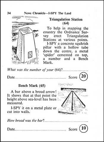
Heights at specific points were calculated relative to Ordnance Datum (the mean level of the sea at Newlyn) and the position of the calculated height indicated on the ground by means of bench marks. Their locations were shown on the 1:2500 plans (25 inches to the mile) and 1:10,560 maps (six inches to the mile) and their later metric equivalents with the spot height given alongside. For those who needed them the latest values of levelling were compiled for sale as bench mark lists.

The design of the bench marks varied with their location and the particular order of geodetic or spirit levelling employed at the time the levelling was carried out. In 1975 J B Harley (see ‘Further Reading’, below) described the various types of bench marks then in use:

(i) Fundamental Bench Marks
There were about 200 of these, usually found at high locations, and consisted of a buried chamber containing two reference points, together with a granite or concrete pillar set beside the chamber with a brass bolt on top. They are not to be confused with the ‘trig pillars’ described above.

(ii) Flush brackets
These consist of metal plates about 90 mm wide and 175 mm long cemented into the faces of buildings. The recorded altitude refers to the small horizontal platform at the point of the broad arrow marked on the plate face; each bracket carries a unique serial number.

(iii) Projecting bracket
They are usually found on the abutments of railway and canal bridges. The reference point is the raised stud on the platform of the bracket.

(iv) Bolt bench marks
These are set in horizontal surfaces, including concrete blocks. They are 60 mm diameter mushroom-headed brass bolts engraved with an arrow and the letters ‘OSBM’.

(v) Cut bench marks
These are the commonest form of bench mark, consisting of a horizontal bar cut into vertical brickwork or similar surfaces. A broad arrow is cut immediately below the centre of the horizontal bar. The height value refers to the centre of the horizontal bar.

(vi) Rivet and pivot bench marks
Bench marks on horizontal surfaces may have a small brass rivet inserted as the reference point. These are described as ‘Rivet’ bench marks and an arrow is cut alongside where this is possible or they may consist if a small hollow cut for a pivot to be inserted at the reference point. They are termed ‘Pivot’ bench marks and also have the arrow symbol.

With the inception of satellite positioning systems the network of triangulation pillars and bench marks was no longer required. Their maintenance by the Ordnance Survey has ceased and as many bench marks are destroyed each year through road and building development they are now becoming uncommon. Many of the prominent ‘trig pillars’ have been preserved by local organizations for sentimental reasons but the bench marks have no guardians and are becoming hard to find.


Note: the Royal Society’s Ramsden theodolite, as used by William Roy, was preserved but sustained irreparable war damage in 1941. The second Ramsden three-foot theodolite, purchased by the Board of Ordnance in 1791, was presented by the Ordnance Survey to the Science Museum, London, in 1876 and is currently (2020) displayed in the exhibition ‘Science City’.


FURTHER READING

J B Harley, Ordnance Survey Maps, a Descriptive Manual (Southampton, 1975), is a useful historical survey of the subject. [12 x 8½ inches (305x215mm)]

Ordnance Survey maps: a concise guide for historians


Richard Oliver, Ordnance Survey maps: a concise guide for historians.
Third Edition, revised, corrected and expanded (The Charles Close Society, 2013)

Tim Owen and Elaine Pilbeam, Ordnance Survey: Map Makers to Britain since 1791 (Southampton and London, 1992). The bicentenary history for the general reader, authoritative and richly illustrated. [282x215mm]

A History of the Ordnance Survey


W A Seymour (ed) and a team of contributors, A History of the Ordnance Survey (Folkestone, 1980). This is a comprehensive and readable history which was published just as the new technologies of the computer and the satellite were beginning to be employed for surveying and mapping. The description of of the triangulation pillars, above, is taken from pages 270-1 of this work.


MILITARY BOUNDARY MARKERS

The use of inscribed boundary stones to indicate the limits of military sites goes back to the eighteenth century. A useful brief account of their history can be found here: https://frontlineulster.co.uk/wd-boundary-stones/ . The earliest were marked B O (Board of Ordnance) but this became W D after the Board was disbanded in 1855 and replaced by the War Department. As an official name this was of short duration, becoming the War Office in 1857. It appears to have been convenient to perpetuate the name War Department for various applications, in particular for the supply of railway locomotives and rolling stock for military purposes both at home and overseas, and also for the designation of military property generally. Thus the Army’s boundary stones continued to be marked W D. The corresponding stones for the Admiralty were marked by a fouled anchor and those for the Air Ministry by A M.

Boundary stones continued to be marked with the broad arrow and W D or the other services’ equivalents until 1964 when the Army, the Royal Navy and the Royal Air Force were placed under unified control in the Ministry of Defence. From that time onwards new boundary stones were marked with M O D and the broad arrow. At an unknown date the design of the arrow also changed from the distinctive three tapered strokes meeting at the top to a simplified symbol recalling those used on direction signs in hospitals or supermarkets. The reasons for changing from a long-standing familiar and recognizable mark to something bland and characterless appear at best opaque.

 
< back to the main Street Furniture page
 
* * *
 
   
  top of page                                                         If you do not see the side menu bar, click here.